Slew rate limited что это
Slew Rate and Slew Rate Limiting
Read all about Ethan’s
book, The Audio Expert.
This article complements the section that describes slew rate on page 595 of my book The Audio Expert (first edition only).
The terms slew rate and slew rate limiting are often used to describe the performance of audio devices, but many people don’t fully understand what these terms mean. The formal definition of slew rate is how quickly a circuit’s output voltage can change, and it’s usually expressed in volts per microsecond. This is different from frequency response, which is independent of output voltage. If a power amplifier is 3 dB down at 50 KHz, it will be reduced by that much whether the input signal is 0.1 volts or 10 volts. However, a circuit’s maximum output capability at high frequencies is a function of its high frequency response and also its slew rate. A preamp might be flat to 50 KHz when passing small signals, but unable to output even 10 KHz at very high levels without distortion.
 |
Figure 1: Sending audio through a series resistor and shunt capacitor as shown creates a low-pass filter. Rapid changes at the input do not pass through to the output because it takes time for the capacitor to charge and discharge.
All audio circuits contain some amount of «stray» capacitance due to the close proximity of connecting wires, PC board traces, and electronic components. Indeed, a capacitor is made from two or more plates of metal that are very close together, but not quite touching. So even when a circuit is meant only to amplify, and not alter the frequency response like a filter, stray capacitance limits the response at very high frequencies. Many amplifiers also include «compensation» capacitors that intentionally roll off very high frequencies above the audible range to prevent ultrasonic oscillation.
You may wonder why charging a capacitor through a resistor creates an output voltage that rises as a curve rather than as a straight line. This is because less and less current is drawn by the capacitor as it charges. When the input voltage first jumps up from zero volts, the capacitor acts as a short circuit across the top and bottom signal wires. So the full input voltage is sent through the resistor, which in turn draws some amount of current. As the capacitor charges, less voltage goes through the resistor, which in turn causes less current to be drawn. For example, when the capacitor is halfway charged, half of the input voltage is across the resistor and the other half is across the capacitor. So only half as much current is drawn through the resistor. When the capacitor is almost fully charged, only a very small amount of current passes through the resistor, further slowing the charging rate.
The charging rate of a capacitor is the same for small or large signals. In other words, the output reaches 80 percent of the input voltage after the same amount of time whether the input is 0.1 volt or 10 volts. However, when the input voltage becomes large enough, the amplifier’s transistors or op-amps may be unable to supply enough current to charge the stray capacitance fast enough to pass high frequencies. At that point the circuit goes into current-limiting, which limits how quickly the stray capacitance can charge. Figure 2 below shows the same stepped input signal as Figure 1, but with the resistor replaced by a current source that outputs a constant amount of current regardless of the capacitor’s present charge level.
 |
Figure 2: Charging (or discharging) a capacitor from a constant current source causes the output voltage to rise (or fall) at a constant rate.
This difference in charging rates using a resistor versus a current source is significant because a sine wave’s rate of change varies at different points along its cycle. As you can see in Figure 3 below, the initial portion of a sine wave rises rapidly compared to the flatter portion along the top.
 |
Figure 3: A sine wave’s voltage rises and falls faster at some parts of its cycle than at others.
When the amount of current available to charge the circuit’s stray capacitance is limited, the fast rising slope of the sine wave becomes more like a triangle wave as shown in Figure 4 below. This change in wave shape creates distortion.
 |
Figure 4: When insufficient current is available to accommodate the steep rising and falling slopes of a high frequency sine wave, it turns into a triangle wave adding new distortion frequencies.
The animation below shows the relation between input voltage, output voltage, and the amount of current drawn when charging a capacitor through a resistor, versus through a constant current source.
 |
Top: When charging a capacitor through a resistor, the initial current drawn is high, so the output voltage rises rapidly. As the capacitor charges, less and less current is drawn, which slows the rate for further charging.
This next section showing how to calculate slew rate is included only for completeness: If a preamplifier has a slew rate of 1 volt per microsecond, then it can output about 10 volts peak-to-peak at 20 KHz without adding slew rate-induced distortion. The formula to determine the minimum slew rate needed for a given frequency and output voltage is:
Slew Rate (in volts per second) = 2 * Pi * Frequency * Required Peak Output Volts
So to output 10 volts peak-to-peak at 20 KHz you need a slew rate of:
2 * 3.14 * 20,000 * 10 = 1,256,000 volts per second
Then divide the result by 1,000,000 to get microseconds:
Ethan Winer has been an audio pro and skeptic for most of his adult life. He now heads up RealTraps, where he designs acoustic treatment products for recording studios and home listening rooms.
Entire contents of this web site Copyright © 1997- by Ethan Winer. All rights reserved.
Slew rate limited что это
И.В.Черных. «Simulink: Инструмент моделирования динамических систем»
9. Библиотека блоков Simulink
9.5.1. Блок ограничения Saturation
Выполняет ограничение величины сигнала.
Выходной сигнал блока равен входному если его величина не выходит за порог ограничения. По достижении входным сигналом уровня ограничения выходной сигнал блока перестает изменяться и остается равным порогу. На рис. 9.5.1 показан пример использования блока для ограничения синусоидального сигнала. На рисунке приводятся временные диаграммы сигналов и зависимость выходного сигнала блока от входного.
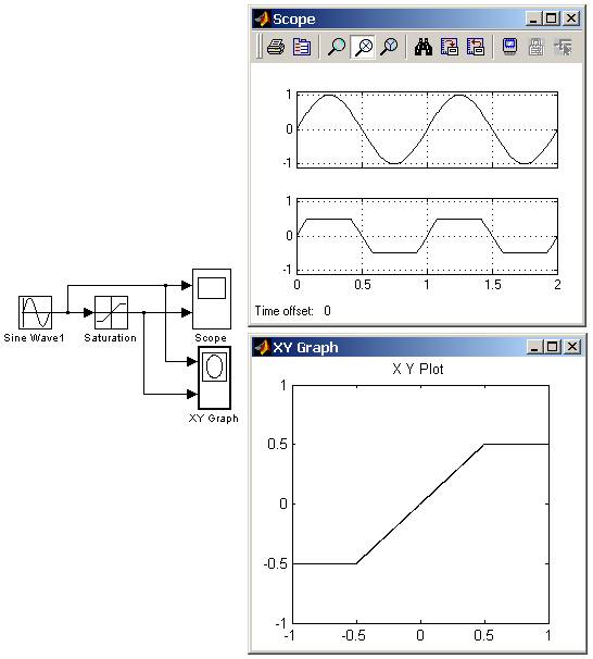
Рис. 9.5.1. Пример использования блока Saturation
9.5.2. Блок с зоной нечувствительности Dead Zone
Реализует нелинейную зависимость типа «зона нечувствительности (мертвая зона)».
На рис. 9.5.2 показан пример использования блока Dead Zone
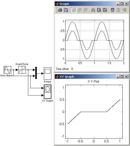
Рис. 9.5.2. Пример использования блока Dead Zone
9.5.3. Релейный блок Relay
Реализует релейную нелинейность.
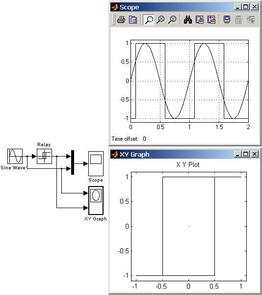
Рис. 9.5.3. Пример использования блока Relay
9.5.4. Блок ограничения скорости изменения сигнала Rate Limiter
Блок обеспечивает ограничение скорости изменения сигнала (первой производной).
Вычисление производной сигнала выполняется по выражению:
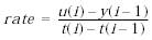 ,
,
Вычисленное значение производной сравнивается со значениями уровней ограничения скорости Rising slew rate и Falling slew rate. Если значение производной больше, чем значение параметра Rising slew rate, то выходной сигнал блока вычисляется по выражению:
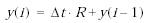 ,
,
Если значение производной меньше, чем значение параметра Falling slew rate, то выходной сигнал блока вычисляется по выражению:
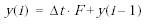 ,
,
Если значение производной лежит в пределах между нижним и верхним уровнями ограничения, то выходной сигнал блока равен входному:
 .
.
На рис. 9.5.4 показан пример использования блока Rate Limiter, при подаче на его вход прямоугольного периодического сигнала.
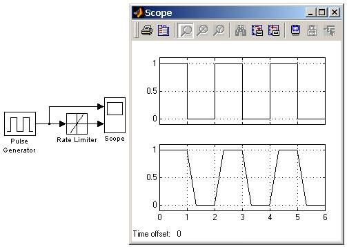
Рис. 9.5.4. Пример использования блока Rate Limiter
9.5.5. Блок квантования по уровню Quantizer
Блок обеспечивает квантование входного сигнала с одинаковым шагом по уровню.
На рис. 9.5.5 показан пример использования блока Quantizer, выполняющего квантование по уровню синусоидального сигнала. Шаг квантования задан равным 0.5.
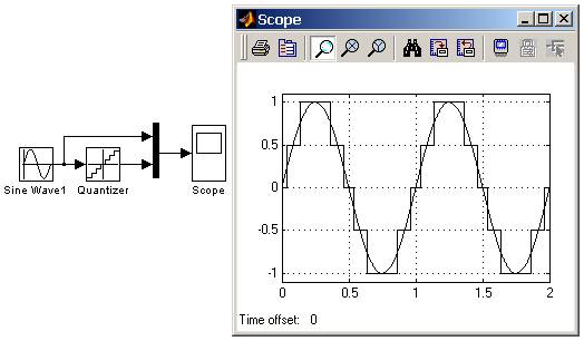
Рис. 9.5.5. Пример использования блока Quantizer
9.5.6. Блок сухого и вязкого трения Coulomb and Viscous Friction
Моделирует эффекты сухого и вязкого трения.
Блок реализует нелинейную характеристику, соответствующую выражению:
 ,
,
На рис. 9.5.6 показан пример использования блока Coulomb and Viscous Friction. Оба параметра блока заданы равными 1.
Рис. 9.5.6. Пример использования блока Coulomb and Viscous Friction
9.5.7. Блок люфта Backlash
Моделирует нелинейность типа “люфт”.
Сигнал на выходе будет равен заданному значению Initial output, пока входной сигнал при возрастании не достигнет значения (Deaband width)/2 (где U – входной сигнал), после чего выходной сигнал будет равен U-(Deaband width)/2. После того как, произойдет смена направления изменения входного сигнала, он будет оставаться неизменным, пока входной сигнал не изменится на величину (Deaband width)/2, после чего выходной сигнал будет равен U+(Deaband width)/2.
На рис. 9.5.7 показан пример работы блока Backlash. Входной сигнал блока гармонический с линейно возрастающей амплитудой.
Рис. 9.5.7. Пример использования блока Backlash
9.5.8. Блок переключателя Switch
Выполняет переключение входных сигналов по сигналу управления.
Threshold – Порог управляющего сигнала.
Блок работает следующим образом:
Если сигнал управления, подаваемый на средний вход меньше, чем величина порогового значения Threshold, то на выход блока проходит сигнал с первого (верхнего) входа. Если сигнал управления превысит пороговое значение, то на выход блока будет поступать сигнал со второго (нижнего) входа.
На рис. 9.5.8 показан пример работы блока Switch. В том случае, когда сигнал на управляющем входе ключа равен 1, на выход блока проходит гармонический сигнал, если же управляющий сигнал равен нулю, то на выход проходит сигнал нулевого уровня от блока Ground. Пороговое значение управляющего сигнала задано равным 0.5.
Рис. 9.5.8. Применение переключателя Switch
9.5.9. Блок многовходового переключателя Multiport Switch
Выполняет переключение входных сигналов по сигналу управления, задающему номер активного входного порта.
Number of inputs – Количество входов.
Блок многовходового переключателя Multiport Switch, пропускает на выход сигнал с того входного порта, номер которого равен текущему значению управляющего сигнала. Если управляющий сигнал не является сигналом целого типа, то блок Multiport Switch производит отбрасывание дробной части числа, при этом в командном окне Matlab появляется предупреждающее сообщение.
На рис. 9.5.9 показан пример работы блока Multiport Switch. Управляющий сигнал переключателя имеет три уровня и формируется с помощью блоков Constant, Step, Step1 и Sum. На выход блока Multiport Switch, в зависимости от уровня входного сигнала, проходят гармонические сигналы, имеющие разные частоты.
Рис. 9.5.9. Применение переключателя Multiport Switch.
Количество входов блока Multiport Switch можно задать равным 1. В этом случае на вход блока необходимо подать векторный сигнал, а сам блок будет пропускать на выход тот элемент вектора, номер которого совпадает с уровнем управляющего сигнала.
На рис. 9.5.10 показан пример использования блока Multiport Switch при векторном сигнале. Временные диаграммы работы для данного примера совпадают с рассмотренными в предыдущем примере.

Рис. 9.5.10. Применение переключателя Multiport Switch при векторном входном сигнале.
9.5.10. Блок ручного переключателя Manual Switch
Выполняет переключение входных сигналов по команде пользователя.
Командой на переключение является двойной щелчок левой клавишей “мыши” на изображении блока. При этом изображение блока изменяется, показывая, какой входной сигнал в данный момент проходит на выход блока. Переключение блока можно выполнять как до начала моделирования, так и в процессе расчета.
На рис. 9.5.11 показан пример использования блока Manual Switch.
Рис. 9.5.11. Пример использования блока Manual Switch.
Slew Rate: What is it? (Formula, Units & How To Measure It)

What is Slew Rate?
In electronics, the slew rate is defined as the maximum rate of output voltage change per unit time. It is denoted by the letter S. The slew rate helps us to identify the amplitude and maximum input frequency suitable to an operational amplifier (OP amp) such that the output is not significantly distorted.
The slew rate should be as high as possible to ensure the maximum undistorted output voltage swing.
Slew rate is a critical factor in ensuring that an OP amp can deliver an output that is reliable to the input. Slew rate changes with the change in voltage gain. Therefore, it is generally specified at unity (+1) gain condition.
Slew Rate Formula
The equation for the slew rate is given by
Where is the output produced by the amplifier as a function of time t.
Slew Rate Units
How to Measure Slew Rate?
The slew rate is measured by applying a step signal to the input stage of the op-amp and measuring the rate of change occurs at the output from 10% to 90% of the output signal’s amplitude. Generally, the applied step signal is large and it is about 1 V.
The slew rate is measured from the output voltage waveform as:
The slew rate can be measured by using an oscilloscope and a function generator.
The circuit used for slew rate measurement is shown in the figure below.
The input and slew limited output voltage waveform are shown in the figure below.
Slew Rate of OP Amp
Slew rate decides the capability of an op-amp to change its output rapidly, hence it decides the highest frequency of the operation of a given op-amp.
The Slew rate of the op-amp can limit the performance of a circuit and it can distort the output waveform if its limit is exceeded.
Op-amps may have different slew rates for positive and negative transitions because of the circuit configuration.
The Slew rate should be ideally infinite and practically as high as possible. The Slew rate of IC 741 op-amp is only about 0.5 which is its major drawback. Therefore, it cannot be used for high-frequency applications.
Slew Rate Limiting in Amplifiers
High Gain at the Input Stage of OP-Amp:
This trans-conductance of amplifiers is typically very high, also at this point, the large open-loop gain of the amplifier is produced. This means that the small input voltage can saturate the input stage. In this saturation condition, the stage produces approximately constant output current and acts as a constant current source. In this condition, the rate of change occurs at the output of the amplifiers is severely limited. This limits the slew rate of an OP-amp.
Frequency Compensation at the Second Stage of OP-Amp:
To provide stability, frequency compensation is used in all op-amps to reduce the high-frequency response have a considerable effect on slew rate. A reduced frequency response limits the rate of change that occurs at the output of the amplifiers and hence it affects the slew rate of an op-amp.
Now, the frequency compensation at the second stage of the op-amp is the low pass characteristic and it is similar to an integrator. Hence constant current input will produce a linearly increasing output. If the second stage has an effective input capacitance C and voltage gain A2, then the slew rate can be expressed as
Where Iconstant is the constant current of the first stage in saturation.
Temperature:
The slew rate is a temperature-dependent parameter. A positive slew rate occurs when a signal is rising and the negative slew rate occurs when a signal is falling. Typically, the slew rate of an amplifier will increase with increasing temperature.
Slew Rate vs Bandwidth
Slew Rate
Slew rate is the maximum rate at which an amplifier can respond to the sudden change of input level. Slew rate can distort (or limit) any signal amplified by an op-amp.
The sinusoidal input signal multiplied by the gain of the op-amp results in a slope which is higher than the slew rate of the op-amp. Hence output waveform will be a straight line instead of a curving section of the sinusoidal. This effect is non-linear. Thus, slewing can modify or distort the shape of a signal.
Bandwidth
The Bandwidth or power bandwidth of an amplifier is the range of frequencies for which all the signal frequencies are amplified almost equally (without distortion) also poles in the transfer function of op-amp leads to low-pass-filter behavior i.e., the amplitude of the signal decreases as frequency increases, and phase shift occurs. This effect is linear and they do not produce distortion into the output signal.
The bandwidth of an op-amp should be as large as possible. It should be capable of amplifying the signal from zero frequency. Thus, the gain of an op-amp should be constant from 0 frequency to infinite frequency. Bandwidth is expressed in hertz.
Relation Between Slew Rate and Full Power Bandwidth
Assuming that the input signal is a sine wave, we can obtain the value of maximum frequency for which the amplifier produces an undistorted output.
Now, for a unity gain non-inverting amplifier, the output is exactly equal to the input.
Differentiate the above equation both the sides we get,
Now, will be maximum when and maximum value of is nothing but the slew rate S. Put it into equation (2) we get,
Where, = the maximum signal frequency in Hz
= the maximum peak voltage of the signal
Rearranging the term in equation (3), we get
The above equation indicates the highest frequency at which the peak-to-peak output voltage swing is equal to the DC output voltage range. In other words, it is the maximum frequency for which the amplifier produces an undistorted output. It is called as full power bandwidth. It is also sometimes described as the slew-rate-limited-bandwidth.
Slew Rate Calculation
An operational amplifier is required to amplify a signal with a peak voltage of 5 volts at a frequency of 20kHz. Find out a slew rate.
Applications of Slew Rate
Electrical4U is dedicated to the teaching and sharing of all things related to electrical and electronics engineering.
slew rate
Смотреть что такое «slew rate» в других словарях:
slew rate — noun (electronics) The rate at which an amplifier can respond to a change in input level • • • Main Entry: ↑slew * * * n. Electronics the maximum rate at which an amplifier can respond to an abrupt change of input level … Useful english dictionary
Slew rate — In electronics, the slew rate represents the maximum rate of change of a signal at any point in a circuit.Limitations in slew rate capability can give rise to non linear effects in electronic amplifiers. For a sinusoidal waveform not to be… … Wikipedia
Slew-Rate — In der Elektronik wird als slew rate (engl.) die Anstiegsrate, Flankensteilheit oder die maximale Anstiegs oder Abfallgeschwindigkeit der Ausgangsspannung einer Verstärker oder Treiberschaltung, speziell eines Operationsverstärkers, bezeichnet.… … Deutsch Wikipedia
Slew rate — In der Elektronik wird als slew rate (engl.) die Anstiegsrate, Flankensteilheit oder die maximale Anstiegs oder Abfallgeschwindigkeit der Ausgangsspannung einer Verstärker oder Treiberschaltung, speziell eines Operationsverstärkers, bezeichnet.… … Deutsch Wikipedia
Slew rate — Vitesse de balayage Effet du slew rate: en rouge la tension désirée, en vert la tension obtenue La vitesse de balayage (ou Slew rate) représente la vitesse de variation maximale que peut reproduire un amplificateur. La v … Wikipédia en Français
Slew rate — En electrónica el Slew Rate es un efecto no lineal en los amplificadores operacionales (A.O.). Representa la incapacidad de un aplificador operacional para seguir variaciones rápidas de la señal de entrada. También se le define como la velocidad… … Enciclopedia Universal
slew rate — the rate of change of the voltage between the positive and negative peaks on the electrogram, or the rate of change in the steepest portion if the electrogram is monophasic … Medical dictionary
slew rate of output voltage — išėjimo įtampos didėjimo sparta statusas T sritis automatika atitikmenys: angl. output voltage increasing rate; slew rate of output voltage vok. Anstiegsgeschwindigkeit der Ausgangsspannung, f rus. скорость нарастания выходного напряжения, f… … Automatikos terminų žodynas
Operationsverstärker mit hoher Slew-Rate — operacinis sparčiai kintančios išėjimo įtampos stiprintuvas statusas T sritis automatika atitikmenys: angl. high slew rate operational amplifier vok. Operationsverstärker mit hoher Slew Rate, m rus. операционный усилитель с высокой скоростью… … Automatikos terminų žodynas
high-slew-rate operational amplifier — operacinis sparčiai kintančios išėjimo įtampos stiprintuvas statusas T sritis automatika atitikmenys: angl. high slew rate operational amplifier vok. Operationsverstärker mit hoher Slew Rate, m rus. операционный усилитель с высокой скоростью… … Automatikos terminų žodynas

Электронные схемы могут указывать минимальные или максимальные пределы скорости нарастания для своих входов или выходов, причем эти ограничения действительны только при некотором наборе заданных условий (например, выходной нагрузке). При задании для выхода схемы, такой как усилитель, спецификация скорости нарастания гарантирует, что скорость перехода выходного сигнала будет по крайней мере заданным минимумом или максимум заданным максимумом. Применительно к входу схемы он вместо этого указывает, что внешняя схема управления должна соответствовать этим ограничениям, чтобы гарантировать правильную работу приемного устройства. Если эти ограничения нарушены, может произойти некоторая ошибка, и правильная работа больше не будет гарантирована.
Например, когда вход в цифровую схему управляется слишком медленно, значение цифрового входа, зарегистрированное схемой, может колебаться между 0 и 1 во время перехода сигнала. В других случаях указывается максимальная скорость нарастания, чтобы ограничить высокочастотную составляющую сигнала, тем самым предотвращая такие нежелательные эффекты, как звон или излучаемые электромагнитные помехи.
В усилителях ограничение скорости нарастания напряжения может привести к нелинейным эффектам. Чтобы синусоидальный сигнал не подвергался ограничению скорости нарастания, допустимая скорость нарастания (в вольтах в секунду) во всех точках усилителя должна удовлетворять следующему условию:
СОДЕРЖАНИЕ
Определение
Измерение
Скорость нарастания может быть измерена с помощью генератора функций (обычно прямоугольной формы) и осциллографа (CRO). Скорость нарастания одинакова, независимо от того, учитывается ли обратная связь.
Ограничение скорости нарастания в усилителях
Существуют небольшие различия между различными конструкциями усилителей в том, как происходит явление поворота. Однако общие принципы такие же, как на этой иллюстрации.
Входной каскад современных усилителей обычно представляет собой дифференциальный усилитель с крутизной характеристики. Это означает, что входной каскад принимает дифференциальное входное напряжение и выдает выходной ток во второй каскад.
Скорость нарастания помогает нам определить максимальную входную частоту и амплитуду, применимые к усилителю, чтобы выходной сигнал не был значительно искажен. Таким образом, становится обязательным проверить таблицу данных для скорости нарастания напряжения устройства, прежде чем использовать его для высокочастотных приложений.
Музыкальные приложения
В электронных музыкальных инструментах схемы нарастания или программно-сгенерированные функции нарастания преднамеренно используются для обеспечения портаменто (также называемого скольжением или задержкой ), когда начальное цифровое значение или аналоговое управляющее напряжение медленно переходит на новое значение в течение определенного периода времени (см. интерполяцию ).