rewrite ingress tag pop 1 symmetric что за команда
Steinkäfer
понедельник, 4 декабря 2017 г.
Cisco EVC
Bridge domain – это виртуальный коммутатор, который передаёт кадры в соответствии с mac таблицей. У каждого bridge-domain-а существует экземпляр таблицы mac-адресов. Отдельных настроек для bridge-domain-а в конфиге Cisco нет, кроме номера в настройке Service instance, хотя на старых IOS bridge-domain необходимо было
Encapsulation (Flexible Service Mapping) – этот параметр в настройках Service instance задает правила выбора пакетов. Например настройка encapsulation dot1q 351 говорит что будут обработаны только кадры с тегом равным 351 (VLAN 351).
Настройка
interface GigabitEthernet0/0/2
no ip address
negotiation auto
service instance 10 ethernet
encapsulation dot1q 762
bridge-domain 351
interface GigabitEthernet0/0/2
no ip address
negotiation auto
service instance 10 ethernet
encapsulation dot1q 762
bridge-domain 351
service instance 20 ethernet
encapsulation dot1q 315,762,700-722
bridge-domain 300
service instance 40 ethernet
encapsulation untagged
bridge-domain 400
service instance 20 ethernet
encapsulation dot1q 315
rewrite ingress tag pop 1 symmetric
bridge-domain 300
service instance 20 ethernet
encapsulation dot1q 315,762,700-722
rewrite ingress tag pop 1 symmetric
bridge-domain 300
service instance 20 ethernet
encapsulation dot1q 315,762,700-722
rewrite ingress tag pop 1 symmetric
bridge-domain from encapsulation
L3 интерфейсы. Маршрутизация.
service instance 20 ethernet
encapsulation dot1q 315
rewrite ingress tag pop 1 symmetric
bridge-domain 300
interface BDI300
ip address 10.0.0.1 255.255.255.0
QoS для EVC
interface BDI760
ip address 10.10.0.15 255.255.255.254
service-policy input QoS_in
EVC by Plumbis
The Problem
On traditional switches whenever we have a trunk interface we use the VLAN tag to demultiplex the VLANs. The switch needs to determine which MAC Address table to look in for a forwarding decision. To do this we require the switch to do two things:
1.) Have the VLAN configured globally
2.) Perform MAC learning in this VLAN
The challenge with this is that it requires us to use finite resources, perhaps without reason. Since the 802.1q VLAN tag is only 12-bits wide we can only configure a maximum of 4096 VLANs. Furthermore switches have a finite amount of CAM space for MAC Learning limiting the number of hosts we can support.
In modern provider and cloud environments there is a need to scale beyond these limitations.
Enter EVCs
Ethernet Virtual Circuits (EVCs) allow us to leverage existing 802.1q VLAN tags in a brand new way. Traditionally the VLAN tag defined both classification (which VLAN) and forwarding (which CAM table to do a MAC lookup in). Now, with EVCs we can separate these concepts; the VLAN tag is used for classification and the Service Instance defines the forwarding action. For example we could allocate VLAN 10 to different customers on every switchport and forward each customer’s traffic across different MPLS Pseudowires, but never actually configure VLAN 10 globally!
How It Works (Ingress)
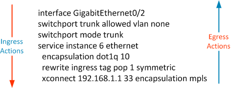
As an 802.1q tagged frame enters an interface that has been configured with an EVC we will determine which EVC it is classified into based on the tags on the frame. Within the EVC we define what action we wish to do with that frame. Let’s take a look at a sample EVC configuration.
switchport trunk allowed vlan none
switchport mode trunk
service instance 6 ethernet
encapsulation dot1q 10
rewrite ingress tag pop 1 symmetric
xconnect 192.168.1.1 33 encapsulation mpls
Now, let’s break down each piece of this configuration.
switchport trunk allowed vlan none
switchport mode trunk
These lines tell the interface that we need to process 802.1q tags as a trunk interface should, however we will not actually pass any VLANs through this interface. VLAN tags received on Service Instance interfaces have no direct relationship to VLANs configured on the switch. Furthermore Service Instance interfaces do not do any MAC learning (except through a bridge-domain VLAN interface, which is discussed later). Because of this we do not want to allow any globally configured VLANs across this trunk interface. We only need to enable VLAN tag processing and let the Service Instance figure out what to do with the frame.
service instance 6 ethernet
This defines the service instance. The number is arbitrary; it has nothing to do with the VLANs that will be processed by this particular Service Instance The “ethernet” keyword is always used.
encapsulation dot1q 10
This is how we map an incoming tag to a service instance. If VLAN tag 10 is received on this interface it will be put into service instance 6.
rewrite ingress tag pop 1 symmetric
Since the incoming tag no longer has any inherent meaning beyond this specific interface we need a way to discard that tag before forwarding the frame on. The rewrite ingress command does just that. In this case we will remove exactly 1 tag, This command is optional and there are a number options that can be done beyond simply removing the tag including, VLAN translation and imposing additional tags. We will discuss some of these options and the “symmetric” keyword a little later.
Finally, what is our forwarding action with that frame?
xconnect 192.168.1.1 33 encapsulation mpls
This tells us that the frame should be sent across the L2VPN MPLS cloud. Since before this we configure the rewrite ingress tag pop 1 symmetric command we will send a frame with no VLAN Tags across the MPLS pseudowire. There are a multiple possible forwarding actions including routing and local switching (connect)
How It Works (Egress)
As a frame is received it will be classified to go out the Service Instance interface based on how it arrived on this switch in the first place. For example if the frame is received across MPLS pseudowire 33, we automatically know it is part of service instance 6
Continuing to work bottom up in the configuration we come to the symmetric part of rewrite ingress tag pop 1 symmetric. Since we popped 1 tag ingress, to be symmetric we need to push 1 tag egress. The symmetric keyword will always be used with the rewrite command.
We determine which tag to impose based on the encapsulation dot1q 10 command. As the frame egresses the interface impose VLAN Tag of 10. Keep in mind that the access layer device that is sending us tagged frames is most likely a traditional Layer-2 switch and needs the tag it sends to be the same tag it receives for proper classification.
Step-by-Step Example
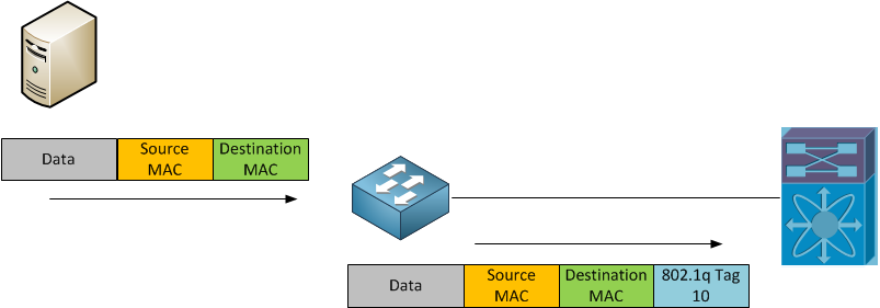
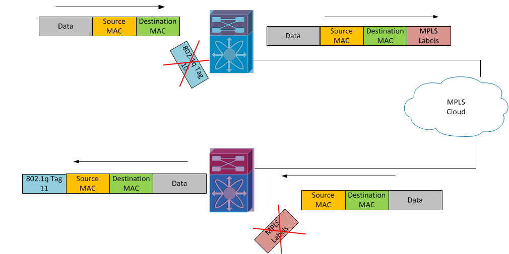
Here’s a sample topology, with two access switches processing different VLANs. The service instance configurations are on PE Blue and PE Purple.
So a few things to note here:
A client connect to the access port will send an untagged frame. This frame will be have VLAN tag 10 added to it by the access layer switch and sent to the PE with the service instance configuration.
The Blue PE will see VLAN tag 10 and place it into service instance 9. Since we have configured the ‘rewrite ingress pop 1 symmetric’ command, we will pop the first tag before applying an MPLS label and forwarding into the MPLS cloud.
As the labeled packet leaves the MPLS cloud we place the untagged frame into PE Red’s service instance 18, based on the “xconnect” command. From there since the “rewrite ingress pop 1 symmetric” command is configured and this is an egress frame we know we need to impose one. The tag imposed is based on the “encapsulation dot1q” configuration, so in this case, VLAN tag 11 is imposed on the frame before sending back out to the access layer switch.
EVC Options
Flexible Matching
One of the things that make EVCs so powerful is their flexible matching criteria. EVCs allow us to classify inbound frames in a highly flexible manner based on 1 or more VLAN tags or CoS values. Here are some examples
Configuration Effect
| encapsulation dot1q 10 | Match the single VLAN tag 10 |
| encapsulation dot1q 25 second-dot1q 13 | Match first VLAN tag 25 and second tag 13 |
| encapsulation dot1q any second-dot1q 22 | Match any double tagged frame with a second tag of 22 |
| encapsulation dot1q 16 cos 4 | Match a single tag 16 when it has CoS value 4 |
| encapsulation dot1q untagged | Match the native (untagged) VLAN |
| encapsulation dot1q default | The catch all class for all traffic not previously classified |
The options here are not exhaustive but just some examples. The other thing to remember about tag matching is that we follow a longest match criteria.
Rewrite Options
Along with a number of flexible matching options we have numerous tag rewrite options.
Configuration Effect
| rewrite ingress tag pop 1 symmetric | remove the top 802.1q tag |
| rewrite ingress tag pop 2 symmetric | remove the top two 802.1q tags |
| rewrite ingress tag translate 1-to-1 dot1q 28 symmetric | remove the top tag and replace it with 28 |
| rewrite ingress tag translate 2-to-2 dot1 22 second-dot1q 23 | remove the top two tags and replace them with 22 and 23 (23 will be the inner tag) |
| rewrite ingress tag push dot1q 56 second-dot1q 55 | push two new tags on top of the existing frame. The top tag will be 56; inner tag of 55 |
Forwarding Options
An EVC can be attached to an MPLS xconnect and we can send the traffic across an MPLS cloud.
For more flexibility EVCs introduce the concept of the Bridge Domain. A Bridge Domain is what is traditionally thought of as a Layer 3 SVI. Unlike the VLAN tags that are being processed by the configured EVCs bridge-domains do require the VLAN to be configured globally on the device and use platform wide resources.
Here is an example of an interface configured with a bridge-domain:
service instance 1 ethernet
encapsulation dot1q 18
rewrite ingres tag pop 1 symmetric
ip address 192.168.1.1 255.255.255.0
The packet, without VLAN tags, will be passed to the VLAN44 interface for normal routing to occur.
We can also tie multiple service instances to the same bridge-domain to make forwarding tagged traffic highly flexible.
service instance 1 ethernet
encapsulation dot1q 18
rewrite ingres tag pop 1 symmetric
service instance 2 ethernet
encapsulation dot1q 66
rewrite ingress tag pop 1 symmetric
ip address 192.168.1.1 255.255.255.0
This configuration will allow either the service instances to speak between one another or out to other routed subnets. More broadly, Vlan 44 will bridge together the two service instances and forward frames based on MAC learning. As a frame enters Service Instance 1, the VLAN tag will be removed, the frame will be passed to Vlan 44 where the destination MAC will be looked up. If the destination is out the other Service Instance, the frame will be placed on Service Instance 2 and a new VLAN tag will be added.
Bridge domains also allow for the configuration of a “split-horizon” (bridge-domain 44 split-horizon) to prevent inter-EVC communication, only allowing for routing outside of the bridge domain.
Finally, we can take multiple EVCs, and send all of them over an MPLS Pseudowire
service instance 1 ethernet
encapsulation dot1q 18
rewrite ingres tag pop 1 symmetric
bridge-domain 44 split-horizon
service instance 2 ethernet
encapsulation dot1q 66
rewrite ingress tag pop 1 symmetric
bridge-domain 44 split-horizon
xconnect 192.168.1.1 55 encapsulation mpls
This will allow us to take two different VLANs and send them to the same MPLS endpoint, removing the VLAN tags in the process. In this scenario we will learn MAC address on both service instances and send them both over the single xconnect, but we prevent traffic on service instance 2 from being sent to service instance 1.
Final Thoughts
Since the way EVCs work is so different from traditional switching not all switching platforms are capable of doing the EVC frame manipulation independently of the forwarding action. Newer platforms like the me3600x or me3800x were designed from the ground up with this kind of capability in mind. The 7600 platform requires newer Ethernet Services (ES) modules to do the additional work that the Supervisor and DFC forwarding engines are unable to do. This guide is also not an exhaustive list of supported platforms or configurations, but merely to demonstrate some deployment options and how traffic forwarding operates in these new EVC environments.
Общие сведения об интерфейсах BVI и BDI
Параметры загрузки
Об этом переводе
Этот документ был переведен Cisco с помощью машинного перевода, при ограниченном участии переводчика, чтобы сделать материалы и ресурсы поддержки доступными пользователям на их родном языке. Обратите внимание: даже лучший машинный перевод не может быть настолько точным и правильным, как перевод, выполненный профессиональным переводчиком. Компания Cisco Systems, Inc. не несет ответственности за точность этих переводов и рекомендует обращаться к английской версии документа (ссылка предоставлена) для уточнения.
Содержание
Введение:
Этот документ помогает понять концепцию BDI (интерфейс домена моста) и BVI (виртуальный интерфейс группы мостов).
Интерфейсы BVI и BDI являются маршрутизируемыми интерфейсами, которые представляют ряд связанных интерфейсов.
Например, предположим, нужно связать два интерфейса на маршрутизаторе и разместить их в одном домене широковещательной рассылки уровня 2. В этом сценарии интерфейс BVI/BDI действовал бы как маршрутизируемый интерфейс для этих двух связанных мостом физических интерфейсов. Все пакеты, входящие в связанные интерфейсы или исходящие из них, должны будут пройти через интерфейс BVI/BDI.
Предварительные условия
Требования
Концепция виртуальных локальных сетей.
Используемые компоненты
Сведения в этом документе основываются на маршрутизаторе ISR (для BVI) и ASR1K (для BDI).
Виртуальный интерфейс мостовой группы: Интерфейс BVI: Для платформ, работающих с IOS
Маршрутизатор не позволяет настраивать два или больше интерфейса уровня 3 в том же домене широковещательной рассылки (два или больше интерфейса в одной подсети). Давайте Давайте Рассмотрим сценарий, в котором нужно подключить два ПК к маршрутизатору и сделать их частью той же подсети в дополнение к доступу к Интернету с обоих ПК.
Этой цели можно достичь с помощью концепции BVI.
bridge 1 protocol ieee
ip address 10.10.10.10 255.255.255.0
ip address 10.10.10.1 255.255.255.0
ip address 10.10.10.2 255.255.255.255
Bridge Domain Interface (BDI): Для платформ, работающих с IOS-XE
Эта концепция очень похожа на BVI, но предназначена для устройств, работающих с IOS-XE.
Ниже приведены некоторые широко используемые термины:
Домен моста представляет домен широковещательной рассылки уровня 2.
Bridge Domain Interface — логический интерфейс, обеспечивающий двунаправленный трафик между сетью с мостовыми подключениями уровня 2 и сетью с маршрутизацией уровня 3.
Виртуальный канал Ethernet (EVC) — сквозное представление единственного экземпляра сервиса уровня 2, предоставляемого заказчику поставщиком. На платформе EVC Cisco домены моста составлены из одного или нескольких интерфейсов уровня 2, известных как экземпляры служб. Экземпляр службы представляет собой экземпляр EVC, созданный по данному порту на данном маршрутизаторе. Экземпляр службы привязан к домену моста на основе конфигурации.
Ниже приведены несколько сценариев, описывающих использование концепции домена моста на платформах IOS-XE:
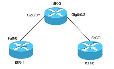
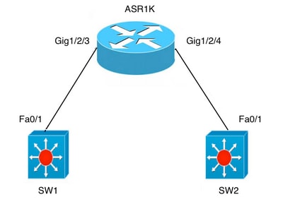
A) Fa0/1 на обоих коммутаторах являются интерфейсами уровня 3 и находятся в одном домене широковещательной рассылки. Настройка интерфейса BDI на ASR не требуется, если нужно просто установить подключение между двумя коммутаторами.
Carrier Ethernet Configuration Guide, Cisco IOS XE Release 3S
Book Title
Carrier Ethernet Configuration Guide, Cisco IOS XE Release 3S
Chapter Title
View with Adobe Reader on a variety of devices
Results
Chapter: Trunk EFP Support
Trunk EFP Support
The Trunk EFP Support feature provides support for Ethernet flow points (EFPs) on trunk ports. A trunk port allows a range of VLANs to be forwarded on a given interface while still maintaining data-plane segmentation between the VLANs.
Finding Feature Information
Your software release may not support all the features documented in this module. For the latest caveats and feature information, see Bug Search Tool and the release notes for your platform and software release. To find information about the features documented in this module, and to see a list of the releases in which each feature is supported, see the feature information table.
Use Cisco Feature Navigator to find information about platform support and Cisco software image support. To access Cisco Feature Navigator, go to www.cisco.com/go/cfn. An account on Cisco.com is not required.
Restrictions for Trunk EFP Support
The rewrite ingress tag pop 1 symmetric command is the only rewrite command that is supported for trunk EFP configurations. The rewrite ingress tag pop 1 symmetric command must be included in the configuration when the Trunk EFP Support feature is enabled.
A bridge-domain number that is part of a trunk EFP configuration cannot be shared by other EFPs under the same port or interface.
Only one trunk EFP can be configured under one port or interface.
All features configured on a trunk EFP (other than encapsulations and bridge-domain assignments) are applied uniformly to all VLANs and bridge domains. If a feature requires VLAN-specific or bridge-domain-specific configuration values, the feature cannot be applied on the trunk EFP. Those special VLANs or bridge domains must be removed from the EFP trunk to form individual EFPs.
Trunk EFP MET supports a maximum of 4078 VLANs and the maximum threshold supported is 20480.
Information About Trunk EFP Support
Benefits of Trunk EFP Support
Static EFPs that are user-configurable.
Dynamic EFPs that are created and maintained during a Cisco Intelligent Services Gateway ( ISG) session.
With this feature, a new EFP type has been added that is intended for use on a trunk port.
A trunk port allows a range of VLANs to be forwarded on a given interface while maintaining data-plane segmentation between the VLANs.

