Remote displacement on Ansys Mechanical APDL
Hi, i would to konw how apply remote displacement on surface in relation to a point. In particular i try to fix all traslation of a surface in relation to a point but i want that this surface have free rotation in relation with this point. In other words i would apply an spherical joint on my body in Ansys Mechanical APDL.
Thanks, Marco Cesari
Comments
You can select the point, create a named selection (say P1) and use the d command to constrain each degree of freedom.
You can read more about them in the manual.
It’s not possible to use keypoint and surface in the command ‘CM’ that you have linked, so how can i relate keypoint and surface?
If i’m not wrong in this way i create an named selection with the keyopoint, but don’t relate the keypoint with surface of my body. My idea is to relate point and the surface of my body constraining only traslational degree of freedom between the surface and keypoint and then fix the point in the absolute coordinate system. In this way i would constrain only traslational degree of freedom of my surface compared to keypoint and would have free the rotational degree of freedom
If you do not want to add stiffness, then there is RBE3 which is for applying remote loads to a surface/edge and that does not add stiffness.
Finally one can use more general MPC type.
Search all this and you will get loads of info on the internet (I have not used these commands for many years but they should still work).
Remote displacement
Based on previous discussions (e.g. this), I implement a displacement on the edge of the beam

and then I shorten the beam length(less elements) to apply a remote displacement:

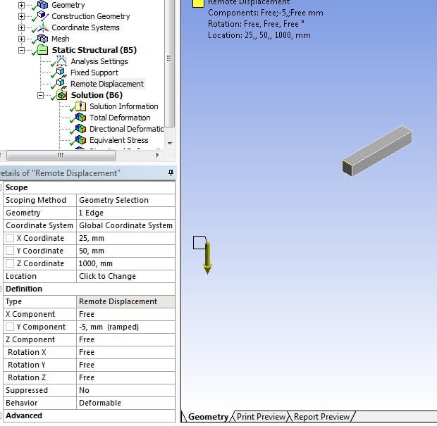
From this I should expect same results right? But they are not the same (displacement as well):


Did I do something wrong?
attached is also the file.
Comments
It’s very commendable that you built models to test your understanding of how things work Jon, excellent!
In the case above, if you want the same stress near the root of a cantilever beam for a full model and one using a remote point, you must apply a force to the tip and not a displacement. If you do that, then the stress at the root will be the same.


yes you are right, it works when remote force is applied.
is there a reason why remote displacement does not give same results?
I mean, if the results are not same, then the usage of remote displacement is limited. But to what case/purpose, if not to the above mentioned one?
Bump on this question from jonsys. Why does remote force only (and not remote displacement) cause both solutions to be the same?
Did you find the reason of the difference on the results between remote displacement and displacement? If so, please share with us. Thanks
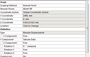
Consider a cantilever beam with a tip load of F that results in a tip displacement d. Now chop off 80% of the beam and replace it with Rigid Elements. If you apply the same tip force to the rigid elements, the beam elements at the base see the exact same shear force and bending moment so the stress will be the same, but the displacement at the tip of the rigid elements will be much less, because 80% of the flexibility was removed.


If you apply the same displacement d to the tip of the rigid elements, you will get much higher stress in the beam elements at the base.
I have seen your Ansys file of remote force.
is it possible to get stress/deformation at the remote force location?
If you want stress at the remote force location then you need material at that location. If you cut away that material, there is nothing there to compute stress from.
If you apply the same displacement d to the tip of the rigid elements, you will get much higher stress in the beam elements at the base. «,»bodyRaw»:»
Consider a cantilever beam with a tip load of F that results in a tip displacement d. Now chop off 80% of the beam and replace it with Rigid Elements. If you apply the same tip force to the rigid elements, the beam elements at the base see the exact same shear force and bending moment so the stress will be the same, but the displacement at the tip of the rigid elements will be much less, because 80% of the flexibility was removed. \n
In my example, I apply a remote force and show the same stress at the base as if you didn’t chop off the end and simply applied a tip force.
If I had applied a remote displacement, Behavior = Rigid, then I would have got a higher stress at the base than the full geometry using the same tip displacement.
Jon used a remote displacement, Behavior = Deformable, which allows deformation at the connected elements, increasing stress there, but reducing stress at the base. This configuration violates beam theory assumptions that plane sections remain planar.
Remote Displacement
With the Remote displacement boundary condition, the guided displacement of a face or volume with a remote point can be specified. It provides advantages compared to the classical displacement boundary condition such as:
In SimScale, the Remote Displacement boundary condition has the following settings:
The parameters of the boundary condition to be defined are:
If the deformable option is used and the number of nodes on the assigned entities is large (>1000), it is advised to use either the MUMPS or PETSC solver instead of Multfront since the performance of Multfront is not optimal for this kind of equations.
Supported Analysis Types
The following analysis types support the usage of the pressure boundary condition:
Remote Point Connections
Behind the scenes, the remote point is connected to all the nodes in the assignment with ‘spider web’ elements. As mentioned above, such elements can be completely rigid, in the case of Undeformable behavior, or flexible in the case of Deformable behavior. In the latter case, the remote point is connected to the nodes by RBE3-constraint.
The specified degrees of freedom are applied to the remote point and broadcasted to the nodes in the assignment via the ‘spider web’ elements. The result is that this boundary condition allows the assigned face to be treated as a single entity, with its movement described with 6 degrees of freedom, constrained or imposed. For example, if the translation degrees of freedom are set to zero, and one rotational degree of freedom is left unconstrained, the assigned face is free to rotate around such an axis.
This is a linear boundary condition, thus it is valid only if small displacements and rotations occur in the area of the applied entity and the remote point itself.
Example Applications
Some cases where the remote displacement boundary condition is often applied are:
Deformation Behavior
To illustrate the difference in the effect of the deformation behavior, let’s see the example of a beam under imposed displacement, resulting in a deflected shape:
 Figure 3: Beam with imposed deflection over the central top face
The deformed shapes for the cases of undeformable and deformable behavior below illustrate the difference between these two conditions. Especially, how in the former case the face deflects with the beam while in the latter it remains flat:
 Figure 4: Beam deflection applied with an undeformable behavior
  Figure 5: Beam deflection applied with a deformable behavior
It is also notable how the undeformable behavior causes a stress discontinuity with respect to the deformable case, in which stresses are smooth and more in line with traditional beam deflection stress distribution.
Tech Tip: Structural Boundary Condition Types
Did you know that there are three main ways to apply force and displacement in a structural analysis? They are:
What are the different behaviors and how can you add a new load to an analysis you wish to restart? Read more below:
Remote Displacement Behaviors
There are three behaviors available with remote boundary conditions:
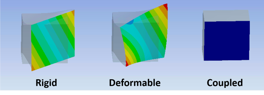
A remote force with the same magnitude & direction is applied with 3 different behaviors :
Rigid – The face shape is not allowed to deform.
Deformable – Load is distributed to the nodes of the face weighted by the distance from the remote point.
Coupled – The specified degree of freedom solutions are equal across the entire face.
The remote boundary conditions are implemented with the Multipoint Constraint (MPC) technology. For more information, see the corresponding section in the Contact Technology Guide of the ANSYS documentation.
Nonlinear Restarts
All of the above loads are compatible with nonlinear restarts but only tabular data after the desired restart point may be modified and only on a pre-existing load. This is because the regular and remote loads actually create surface effect elements (SURF154) to implement the load behind the scenes. While this confers several benefits, such as the ability to have overlapping loads on the same face, it is not compatible with nonlinear restarts since adding new elements would change the model too much. Direct forces and pressures are applied directly to the nodes, however, and avoid this restriction. This functionality is not available for direct displacements since a displacement of 0 is a constraint and would invalidate the restart points.
To add an entirely new load (force/pressure only) to an analysis:
Did you find this useful? Sign up for our newsletter below to receive tips like this and more every month:
What is the difference between remote displacement and displacement in ansys workbrench?
I am wondering that why a displacement it does not include DOF of rotation options? It means the displacement assumes that all rotations are free automatically or all rotations are ZERO. which one Is that right?
I am looking forward hearing you dear experts
Comments
A Displacement Boundary Condition only covers the Translational DOF.
Solid elements don’t have rotational DOF at the nodes.
Shell and Beam elements do have rotational DOF at the nodes. When a Displacement BC is applied to those nodes, the rotational DOF are considered to be Free.
If you want zero rotation at the nodes then you can use a Fixed Support, which sets all translations and all rotations to be zero.
In Workbench, there is a Boundary Condition called Fixed Rotations where you can set all or specific rotational DOF to be zero.
Thank you always for your kind support. One more question, please? I have done a numerical analysis of the following experimental study, but I found the beam flanges’ different deformation behaviors during the numerical analysis than the experimental results. Here, A, B, and C points are constrained. For example, A point «C» is assumed by fixed support while some directional DOFs are considered in the points «A» and «B» relatively given coordinate system. I have tried it by diverse variants of DOF to find accurate results in each point. It demands a lot of patience to finish the calculation time.

Figure-1. General apparatus

Figure-2. Front side buckling behaviors

Figure-3. Back side buckling behaviors
Firstly, I assumed that the rotation Y is constant (0), and other DOF are free in the beam tip. In the point «B,» Z component and Rotation X are constant because I thought these two vertical columns fully constrained those movements. Unfortunately, the analysis shows me a different shape of deformation behavior than the experimental results. In the analysis shell elements are considered.


Figure-4. Back and front side buckling behaviors.
Secondly, the rotation X is constant (0), and other DOF are free in the beam tip. In the point «B,» Z component and Rotation X are constant. Again the analysis shows me a different shape of deformation behavior than the experimental results. Here, the deformation behaviors of the first and second variants were similar.


Thirdly, the rotation X and Y are constant (0), and other DOF are free in the beam tip. In the point «B,» Z component and Rotation X are constant. The analysis were terminated and again shows me a different shape of deformation behavior than the experimental results.


How to know that which DOF of the point A and B acceptable in the numerical analysis? Could you check it out for me please? Please kindly see the attached file.